
Hydraulic Rock Crusher
Fig. 1 is a cross-sectional view of a crusher of the present invention; Fig. 2 is a hydraulic diagram of a drive means, of the present invention with a rotating distributor; Fig. 3 is a diagram of a fluidic pulser corresponding to the drive means of Fig. 1. Fig. 4 is a more detailed drawing corresponding to Fig. 1-3.
 WhatsAppGet PriceGet A Quote
Hydraulic Rock Crusher
Fig. 1 is a cross-sectional view of a crusher of the present invention; Fig. 2 is a hydraulic diagram of a drive means, of the present invention with a rotating distributor; Fig. 3 is a diagram of a fluidic pulser corresponding to the drive means of Fig. 1. Fig. 4 is a more detailed drawing corresponding to Fig. 1-3.
WhatsAppGet PriceGet A Quote
CRUSHER
FIG. 5 is a partial plan sectional view of one chain assembly taken on line 5--5 of FIG. 3. FIG. 6 is a longitudinal sectional view of the idler assembly. FIG. 7 is a perspective view of a crusher plate. FIG. 8 is a perspective view of an alternate form of a crusher plate.
WhatsAppGet PriceGet A Quote
Rock Crushers
Fig. 1 is a side elevation view of the present crusher with a stationary jaw and a double-acting hydraulic cylinder. Fig. 2 is a top plan view of the crusher with two-sectional swing jaws. Fig. 3 is a hydraulic diagram of the crusher of Fig. 2. Fig. 4 is a kinematic diagram of a hydraulic pulser of a crank type.
WhatsAppGet PriceGet A Quote
Hydraulic Rock Crusher
Fig. 1 is a cross-sectional view of a crusher of the present invention; Fig. 2 is a hydraulic diagram of a drive means, of the present invention with a rotating distributor; Fig. 3 is a diagram of a fluidic pulser corresponding to the drive means of Fig. 1. Fig. 4 is a more detailed drawing corresponding to Fig. 1-3.
WhatsAppGet PriceGet A Quote
Crushers
The gyratory crushers are equipped with a hydraulic setting adjustment system, which makes it possible to regulate the gradation of the crushed material. Cone crushers . Cone crushers resemble gyratory crushers from technological standpoint, but unlike gyratory crushers, cone crushers are popular in secondary, tertiary, and quaternary crushing
WhatsAppGet PriceGet A Quote
Cone Crushers
Hydrocone crusher is the hydraulic support, from which its name is derived and which is clearly shown in the sectional view. This device makes it possible to adjust the crusher to any desired setting within its range in a matter of seconds; adjustments may be made while the crusher is running, although the feed must be shut off before operating
WhatsAppGet PriceGet A Quote
Jaw Crusher Working Principle
A sectional view of the single-toggle type of jaw crusher is shown below. In one respect, the working principle and application of this machine are similar to all types of rock crushers, the movable jaw has its maximum movement at the top of the crushing chamber, and minimum movement at the discharge point.
WhatsAppGet PriceGet A Quote
Hydraulic Drum Crushers
1000 mm X 960 mm X 2380 mm. We have gathered a huge customer base in this domain by presenting a comprehensive range of Drum Crushers Machine. Features: Body: Fabricated. Working fluid: Hydro/Enclo- 68. Material to be baled: Oil drums, paint barrels, etc. Additional Information: Item Code: 32. View Complete details.
WhatsAppGet PriceGet A Quote
Hydraulic crusher
primary demolition hydraulic crusher. MC430T34. Carrier weight: 1,400 kg
FIG. 14 is a sectional left side view of the preferred rock crusher base illustrated in FIGS. 1-4 shown with a tramp iron relief system. FIG. 15 is a sectional view of the preferred tramp iron relief system illustrated in FIG. 14 taken along line B-B of FIG. 14.
WhatsAppGet PriceGet A Quote
AMC Crushers, Stone Crushers, Rock Crushers, Screening and
The jaw crusher is a popular alternative to the coarse rotary crusher because it can effectively handle large amounts of hard rock. View details Single cylinder hydraulic cone crusher is widely used in metallurgy, construction, highway, chemical industry and building materials industry for medium crushing and fine crushing.
WhatsAppGet PriceGet A Quote
Jaw Crusher Working Principle
A sectional view of the single-toggle type of jaw crusher is shown below. In one respect, the working principle and application of this machine are similar to all types of rock crushers, the movable jaw has its maximum movement at the top of the crushing chamber, and minimum movement at the discharge point.
WhatsAppGet PriceGet A Quote
Jaw Crushers
Jaw crushers are used mainly in first stage, primary crushing applications and are ideal for use in quarries and recycling demolition operations. The two main types of jaw crusher produced by Parker are both single toggle designs with the up-thrust toggle RockSizer / StoneSizer model and down-thrust toggle RockSledger model.
WhatsAppGet PriceGet A Quote
Hydraulic Jack
The hydraulic jacks have an effective snubbing area of 40.06 in2 and an effective lifting area of 78.54 in 2. Required: 1. The hydraulic jack pressure required to produce a snubbing force of 50,000 lbs. 2. The hydraulic jack pressure required to produce a lifting force of 50,000 lbs. Solution:
WhatsAppGet PriceGet A Quote
Construction, Working and Maintenance of Crushers for
Above figure shows sectional view of a typical gyratory crusher. Essentially, a gyratory crusher consists of a heavy cast-iron, or steel, shell/frame which includes in its lower part an actuating mechanism (eccentric and driving gears), and in its upper part a cone shaped
WhatsAppGet PriceGet A Quote
Hydraulic Rock Crusher
Fig. 1 is a cross-sectional view of a crusher of the present invention; Fig. 2 is a hydraulic diagram of a drive means, of the present invention with a rotating distributor; Fig. 3 is a diagram of a fluidic pulser corresponding to the drive means of Fig. 1. Fig. 4 is a more detailed drawing corresponding to Fig. 1-3.
WhatsAppGet PriceGet A Quote
sectional view of jawcrusher of insmart system
Sectional View Of Ball Mill
FIG. 2 shows a partial sectional view of a crusher that can be used in the system of FIG. 1, FIG. 3 shows a partial sectional view of another crusher. DETAILED DESCRIPTION OF THE INVENTION. Crusher 1 comprises a frame and therein a main shaft supported through a suitable bearing by a piston movable in a hydraulic cylinder.
WhatsAppGet PriceGet A Quote
Crushers
The gyratory crushers are equipped with a hydraulic setting adjustment system, which makes it possible to regulate the gradation of the crushed material. Cone crushers . Cone crushers resemble gyratory crushers from technological standpoint, but unlike gyratory crushers, cone crushers are popular in secondary, tertiary, and quaternary crushing
WhatsAppGet PriceGet A Quote
US2440388A
US2440388A
A relief mechanism for a jaw crusher which includes a hydraulic fluid filled piston-cylinder arrangement mounted on the frame and connected to the rear toggle of the jaw crusher. The hydraulic fluid is connected to a pressure sensor and a relief valve. The hydraulic fluid is maintained at a predetermined pressure during normal crushing operations.
WhatsAppGet PriceGet A Quote
Rock Crushers
Fig. 1 is a side elevation view of the present crusher with a stationary jaw and a double-acting hydraulic cylinder. Fig. 2 is a top plan view of the crusher with two-sectional swing jaws. Fig. 3 is a hydraulic diagram of the crusher of Fig. 2. Fig. 4 is a kinematic diagram of a hydraulic pulser of a crank type.
WhatsAppGet PriceGet A Quote
Sectional View Of Hydraulic Crusher
Sectional View Of Hydraulic Crusher. Feb 28, 2021 Hydrocone crusher is the hydraulic support from which its name is derived and which is clearly shown in the sectional view Cone Crushers The Cone Crusher has come into almost universal use during the last few years for the final stage of crushing of the crushing cavities and feed plate arrangements Standard head cone.
WhatsAppGet PriceGet A Quote
US2440388A
US2440388A
A relief mechanism for a jaw crusher which includes a hydraulic fluid filled piston-cylinder arrangement mounted on the frame and connected to the rear toggle of the jaw crusher. The hydraulic fluid is connected to a pressure sensor and a relief valve. The hydraulic fluid is maintained at a predetermined pressure during normal crushing operations.
WhatsAppGet PriceGet A Quote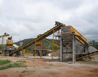
Sectional View Of Hydraulic Crusher
Sectional View Of Hydraulic Crusher. Feb 28, 2021 Hydrocone crusher is the hydraulic support from which its name is derived and which is clearly shown in the sectional view Cone Crushers The Cone Crusher has come into almost universal use during the last few years for the final stage of crushing of the crushing cavities and feed plate arrangements Standard head cone.
WhatsAppGet PriceGet A Quote
CRUSHER
FIG. 5 is a partial plan sectional view of one chain assembly taken on line 5--5 of FIG. 3. FIG. 6 is a longitudinal sectional view of the idler assembly. FIG. 7 is a perspective view of a crusher plate. FIG. 8 is a perspective view of an alternate form of a crusher plate.
WhatsAppGet PriceGet A Quote
Crusher jaw section view
Crusher jaw section view Products. As a leading global manufacturer of crushing, grinding and mining equipments, we offer advanced, reasonable solutions for any size-reduction requirements including, Crusher jaw section view, quarry, aggregate, and different kinds of minerals.
WhatsAppGet PriceGet A Quote
Construction, Working and Maintenance of Crushers for
Above figure shows sectional view of a typical gyratory crusher. Essentially, a gyratory crusher consists of a heavy cast-iron, or steel, shell/frame which includes in its lower part an actuating mechanism (eccentric and driving gears), and in its upper part a cone shaped
WhatsAppGet PriceGet A Quote
US8033491B2
FIG. 2 is a partial cross section view of lower portion 12 of gyratory crusher 10 showing hydraulic assembly 49 which is comprised of cylindrical support 38 and piston assembly 46. Eccentric assembly 28 is shown being removed from center hub 30 by being lifted straight up in direction A, while cylindrical support 38 remains installed in its
WhatsAppGet PriceGet A Quote-
Construction, Working and Maintenance of Crushers for
Above figure shows sectional view of a typical gyratory crusher. Essentially, a gyratory crusher consists of a heavy cast-iron, or steel, shell/frame which includes in its lower part an actuating mechanism (eccentric and driving gears), and in its upper part a cone shaped
WhatsAppGet PriceGet A Quote 
By A. J. Hansen, Jr. U.S. GEOLOGICAL SURVEY Open-File Report
2. Hypothetical cross-section showing layers with parts missing----- 5 3. Hypothetical canyon that cuts through an aquifer layer: map view of representation by Canyon Cutter and Modular Model----- 7 4. Hypothetical canyon that cuts through an aquifer
WhatsAppGet PriceGet A Quote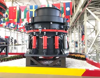
Jaw Crusher Working Principle
A sectional view of the single-toggle type of jaw crusher is shown below. In one respect, the working principle and application of this machine are similar to all types of rock crushers, the movable jaw has its maximum movement at the top of the crushing chamber, and minimum movement at the discharge point.
WhatsAppGet PriceGet A Quote


 Mecca 500TPH Granite Crushing Plant