
DESIGN AND ANALYSIS OF A HORIZONTAL SHAFT IMPACT CRUSHER
Chapter 5 CAD Drawings /model Proposed design of hammer/ blow bar 33 Proposed design of rotor assembly 34 Front view of the proposed crusher 35 Side view of the proposed crusher 36 Irregular dispersal of feed over the crushing chamber Deficiency of feed control.
 WhatsAppGet PriceGet A Quote
Feed check valve assembly + drawing | 3D CAD Model Library
Feed check valve assembly + drawing. Ohm Vaghela. October 17th, 2021. This contains a feed check valve assembly and drawing with mks unit system. for dimensions refer to the pdf file attached. sorry for inconvenience in making pdf file cumbersome. Show more... View Files.
WhatsAppGet PriceGet A Quote
Tablet feed assembly
A feed assembly for use in filling a container with tablets or other materials, comprising: The present construction also helps to support the weight of the tablets and thus reduces tablet crushing. BRIEF DESCRIPTION OF THE DRAWINGS. FIG. 1 is a side elevation of a feed assembly constructed in accordance with the present invention.
WhatsAppGet PriceGet A Quote
COLLEGE OF ARCHITECTURE AND ENGINEERING SCHOOL OF
ii ACKNOWLEGEMENT We would like first to give our sincere gratitude to the Almighty God for guiding us through this project We also thank our families and friends who gave us physical, financial and emotional assistance
WhatsAppGet PriceGet A Quote
Construction, Working and Maintenance of Crushers for
6 Construction, Working and Maintenance of Crushers for Crushing Bulk Materials www.practicalmaintenance.net shown in above figure, a closed circuit crushing system is a means of controlling product top size by screening the product and then returning oversize material to the feed end of the
WhatsAppGet PriceGet A Quote
Troubleshooting the Wire Feed System | Fabricating and
4. Feed the wire into the system all the way to the contact tip. 5. Set the wire feed speed to the maximum setting (or if you will never exceed a given wire feed speed, set it at 20% above your maximum setting). 6. Feed and stop the wire as the adjustment screw is tightened ensuring that the wire does not over-spool or de-coil off of the spool.
WhatsAppGet PriceGet A Quote
Crushers
Material below setting in the feed 10-30% (but no filler and fines 0-4 mm normally). Maximum feed size. Reduction ratio must be limited to 3 (-4). Recommended max feed size is 50 mm. Correct feed distribution. Feed distribution should be non segregated and evenly distributed around crushing cavity. Setting closer to required product; Correct
WhatsAppGet PriceGet A Quote
COLLEGE OF ARCHITECTURE AND ENGINEERING SCHOOL OF
ii ACKNOWLEGEMENT We would like first to give our sincere gratitude to the Almighty God for guiding us through this project We also thank our families and friends who gave us physical, financial and emotional assistance
WhatsAppGet PriceGet A Quote
ENGINEERING GUIDE Screw Conveyors
2 . Capacity or feed rate of bulk material to be conveyed expressed in pounds per hour, tons per hour, or cubic feet per hour 3 . required distance and incline the bulk material is to be conveyed 4 . design conditions such as materials of construction, inlet feed conditions and operating temperature
WhatsAppGet PriceGet A Quote
BOMs and Assembly Drawings
With the release of SOLIDWORKS 2010, SOLIDWORKS added some neat features when working with assembly drawings and BOMs. First off, you will notice that when you select the BOM it now has a big, move icon that is now much easier to grab and move the BOM around. The best of the bunch is the ability to move the BOM to a second sheet.
WhatsAppGet PriceGet A Quote
AMIT 135: Lesson 5 Crushing – Mining Mill Operator Training
This means that the number of crushing stages can be reduced depending on the feed size accepted by primary grinding stage. Image of a “Classical” 3-stage ore crushing prior to rod mill [image: (135-5-1)] Diagram of Typical 1-2 stage ore crushing prior to AG-SAG mill [image: (135-5-2)] Calculation of Reduction Ratio in Crushing
WhatsAppGet PriceGet A Quote
What is Front End Engineering Design or FEED Engineering
Front End Engineering Design or FEED is an engineering design approach adopted prior to detailed engineering, procurement, and construction. It is an important engineering design phase that is used to control project expenses and thoroughly plan a project before bid submission.
WhatsAppGet PriceGet A Quote
Feed_check_valve_Assembly | 3D CAD Model Library | GrabCAD
Feed_check_valve_Assembly. Manoj kumar [ MK] December 31st, 2019. Feed Check valve use To allow the feed water to pass/enters into the boiler. To prevent the back flow of water from the boiler...
WhatsAppGet PriceGet A Quote
Gyratory Crusher Components
Gyratory Crusher Components. The Gyratory Crusher is made up of six main components , Base, Main frame and concave liners, Drive assembly, Mantle, Spider arm assembly, Oil system. The base is the section of the crusher that provides an entry point for the drive assembly and oil system. It also provides support for the working surface of the
WhatsAppGet PriceGet A Quote
Feed check valve assembly + drawing | 3D CAD Model Library
Feed check valve assembly + drawing. Ohm Vaghela. October 17th, 2021. This contains a feed check valve assembly and drawing with mks unit system. for dimensions refer to the pdf file attached. sorry for inconvenience in making pdf file cumbersome. Show more... View Files.
WhatsAppGet PriceGet A Quote
Assembly and Details machine drawing pdf
Begin with the view from the front, by drawing first, the main parts of the machine and then adding the rest of the parts, in the sequence of assembly. 7. Project the other required views from the view from the front complete views. 8. Mark the location and overall dimensions and add the part numbers on the drawing. 9.
WhatsAppGet PriceGet A Quote
(PDF) Design of Impact stone crusher machine
• Assembly drawings and its instructions also are. • Large feed port, deep crushing chamber, These problems could be unchangeable feed rate, hidden steel part between rocks and wastage
WhatsAppGet PriceGet A Quote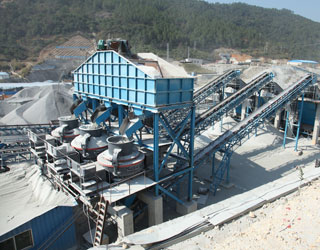
2018
Q. Draw the assembly drawings of the differential mechanism and speed reducer part drawings (SOURCE: Machine drawing book by KL Narayana, P Kannaiah, K V Reddy ) of which are shown below. (Extract dimensions from the internet, or they will be provided) Part Drawings of the Differential mechanism
WhatsAppGet PriceGet A Quote
CHAPTER
3. Choose a proper scale for the assembly drawing. 4. Estimate the overall dimensions of the views of the assembly drawing and make the outline blocks for each of the required view, leaving enough space between them, for indicating dimensions and adding required notes. 5. Draw the axes of symmetry for all the views of the assembly drawing. 6.
WhatsAppGet PriceGet A Quote
DESIGN, FABRICATION AND TESTING OF A LABORATORY SIZE
crushing equipment for a specific purpose is influenced by many factors some of which are downstream of the crushing plant. Mineral processing is a complex operation. The principal procedure is crushing, that is the size reduction in the size of the fragmented rocks so that it can be rendered to another stage for further processing.
WhatsAppGet PriceGet A Quote
TST jaw crusher
The active feed opening of the jaw crusher chamber ensures that any occasional oversize material will be gripped and quickly pulled into the crusher. Once the jaw plates pull in the material, its steep nip angle ensures continual grip and efficient crushing of even the hardest material. Active feed opening can grip material at the inlet
WhatsAppGet PriceGet A Quote
Assembly and Details machine drawing pdf | Mechanical
CHAPTER
Maintenance of the wear components in both gyratory and cone crushers is one of the major operating costs. Wear monitoring is possible using a Faro Arm (Figure 6.10), which is a portable coordinate measurement machine.Ultrasonic profiling is also used. A more advanced system using a laser scanner tool to profile the mantle and concave produces a 3D image of the crushing chamber (Erikson, 2014).
WhatsAppGet PriceGet A Quote
DEM-based design of feed chute to improve performance of
The effect of feed chute design on tertiary cone crusher performance at the Sarcheshmeh copper complex was studied by an in-house developed DEM software called KMPC DEM ©. To simulate the overall crushing circuit, the multi-geometry procedure by improving the routines of object files importing into the simulation environment was implemented in DEM codes.
WhatsAppGet PriceGet A Quote
RM 120GO!
technical data WORKING POSITION RM 120GO! – TRACKED MOBILE IMPACT CRUSHER Feed material size Inlet opening Crusher unit RUBBLE MASTER impact crusher with 2 or 4 hammers, 3 rotor speeds Radio control for crushing and manoeuvring operations Feed unit Asymmetric vibro feeder with 4 m3 and 2 vibrator motors each 3.1 kW, loading height 3,200 mm, effective feed length and width: 3,100 x 2,200 mm
WhatsAppGet PriceGet A Quote
CN212814208U
the box body assembly comprises a box body, a support frame and a feed hopper, the box body is supported on the ground through the support frame, a feed inlet is formed in the upper end face of the box body, a discharge outlet is formed in the bottom of the box body, the feed hopper is installed at the feed inlet, and a first crushing bin, a second crushing bin and a mixing bin are arranged in
WhatsAppGet PriceGet A Quote
Crushing
Crushing Astec designs and manufactures a wide range of quality crushing equipment that is technology-driven and durably-designed for modern crushing operations. Our state-of-the-art machinery is specifically built to accommodate a variety of applications and materials with high productivity and profitability.
WhatsAppGet PriceGet A Quote
Industrial Solutions Gyratory crushers
G Eccentric bearing assembly with inner bushing that can be replaced, or in The feed material that is fed into the crushing chamber from above is progressively crushed between the crushing elements (C), finally feed opening. Arrangement drawing with fitting dimensions and loads on request.
WhatsAppGet PriceGet A Quote
ASSEMBLY DRAWING OF FEED CHECK VALVE
This video make by Vishwakarma Engineering Drawing Classes, Bhilai Nagar.
WhatsAppGet PriceGet A Quote
Jaw Crusher Working Principle
A sectional view of the single-toggle type of jaw crusher is shown below. In one respect, the working principle and application of this machine are similar: the movable jaw has its maximum movement at the top of the crushing chamber, and minimum movement at the discharge point. The motion is, however, a more complex one than the Dodge motion, being the resultant of the circular motion of the
WhatsAppGet PriceGet A Quote
Crushing and screening solutions
''s experience and competence in crushing and screening technology ensures that we provide equipment that is the best in the world. The use of premium-quality components ensures that your equipment runs at high performance, cost efficiently and safely. depending on the feeding method and on feed characteristics such as gradation
WhatsAppGet PriceGet A Quote


 Mecca 500TPH Granite Crushing Plant